MEASUREMENT TECHNOLOGY
RF measurement technology for antennas, filters and amplifiers
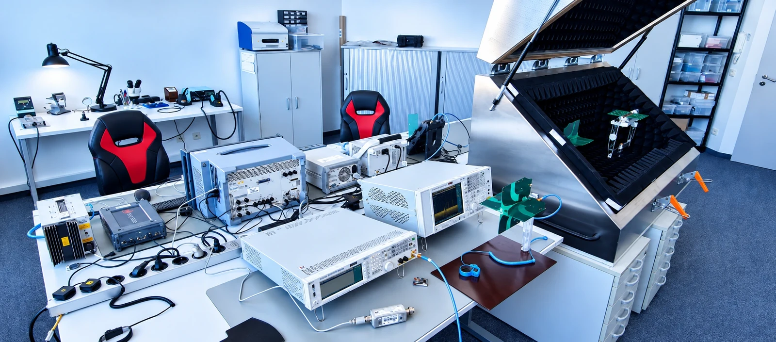
We characterize antennas and RF assemblies with network analysis, signal and spectrum analysis, noise measurement and measurements in our anechoic chamber.
Connect development data and real structures
A meaningful measurement begins with the test objective. We determine which parameter is required, the frequency band in which it must be measured and the installed condition represented by the device under test. We adapt calibration, reference planes, cables and adapters to the setup. This allows targeted investigation of losses, mismatch and active gain in the signal path.
S-parameters, impedance matching and decoupling
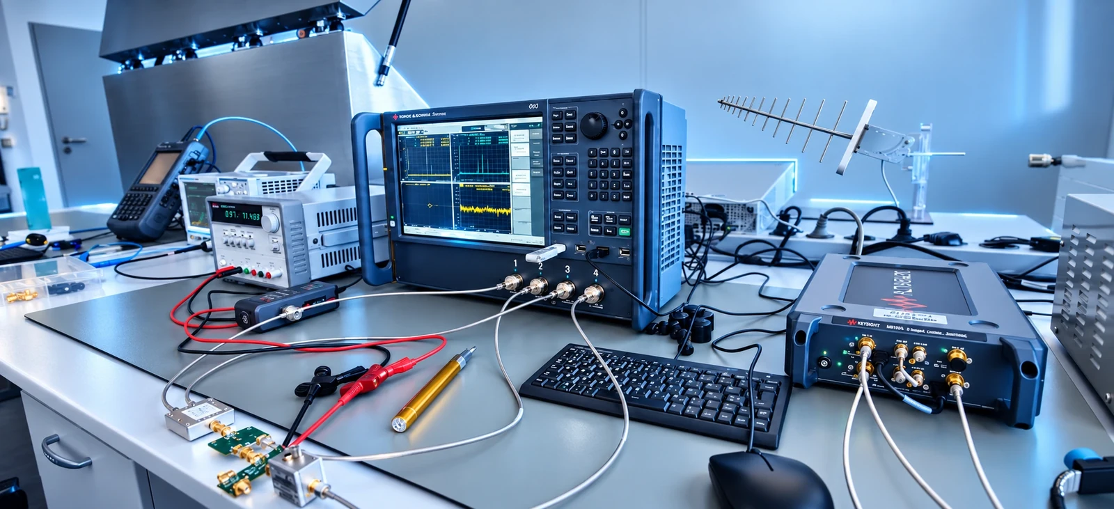
We use vector network analysis to measure antennas, filters, transmission lines, couplers and other RF assemblies. Relevant S-parameters describe input and output matching, insertion loss and isolation. For multiple antennas, we investigate mutual coupling. We select the calibration method and reference planes to suit the device under test and account for the test cables. Our network analyzers have specified instrument frequency ranges up to 26.5 GHz. The usable range of each measurement also depends on the accessories, setup and test objective.
- S11 and S22, bandwidth and matching variants
- S21, insertion loss and gain
- Isolation, coupling and critical transitions
Spectra, power and active receive paths
Signal and spectrum analysis support the investigation of desired signals, interference components and harmonics. For active assemblies, we assess output power, gain, noise figure and intermodulation in the agreed operating state. Power supply, input level and frequency plan are part of the measurement configuration. A noise source with a specified source frequency range of 10 MHz to 18 GHz is available for noise measurements. This source range does not establish a general measurement limit for all noise-figure, gain or IP3 measurements. We select the appropriate method for the assembly.
- Spectral evaluation and power measurement
- Gain and noise figure in the receive path
- IP3 and intermodulation at fixed signal levels
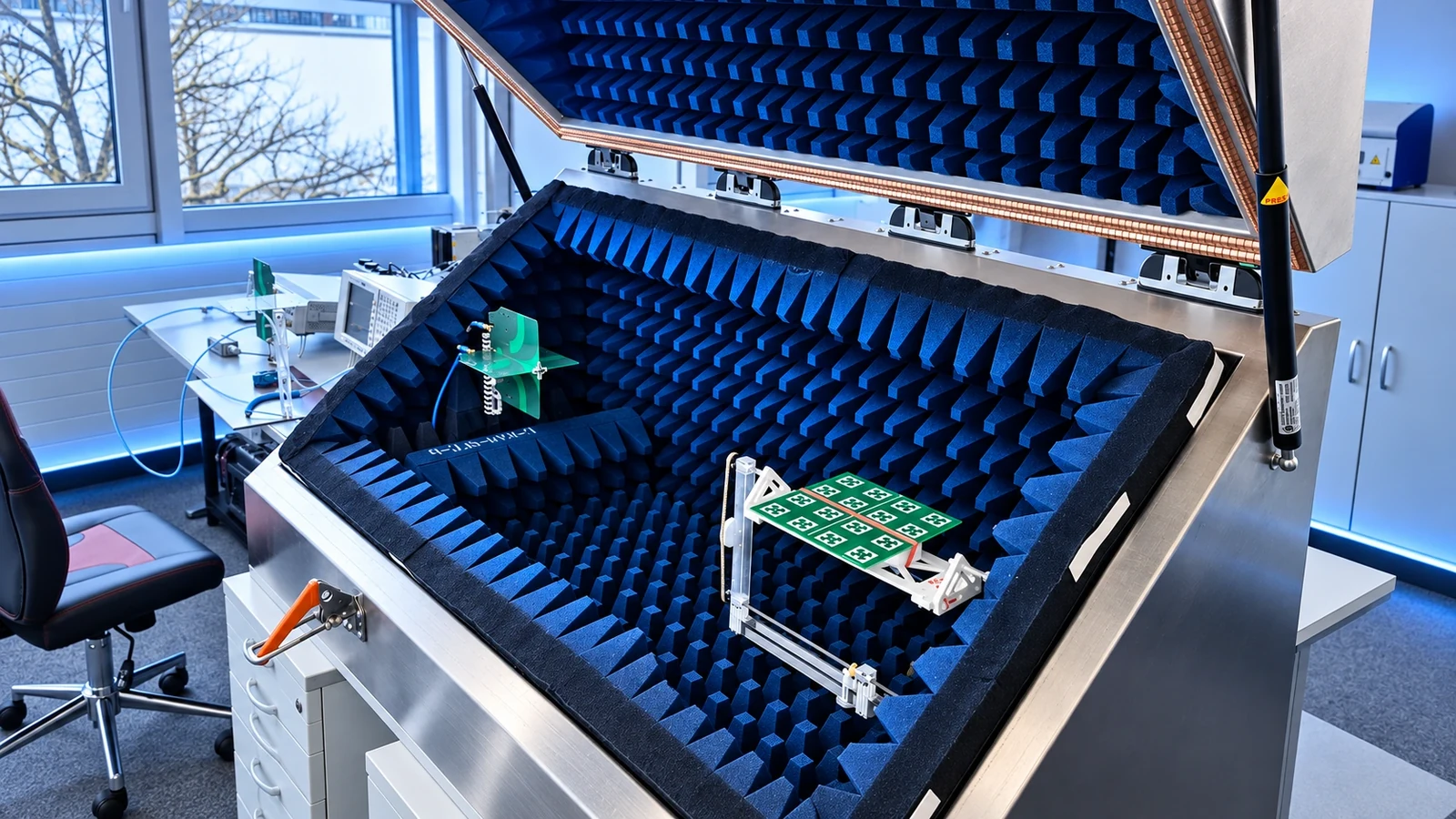
Antenna measurements in the anechoic chamber
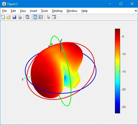
In our anechoic chamber, we examine antenna radiation patterns, gain and efficiency. The setup is crucial: an antenna in free space may behave differently from one inside a product enclosure with a battery, cables and electronics. We compare integration variants under documented conditions and include the antenna feed and feed lines in the assessment. Measurement geometry, reference conditions and evaluation procedures are defined for the frequency band and device under test. The results complement impedance measurements and enable comparison with the electromagnetic model.
- Directional characteristics and relevant installation positions
- Gain and efficiency according to the test plan
- Comparison of antenna positions and housing variants
Automation and traceable results
We use MATLAB to support measurement control, data preparation and visualization. Repeatable processes and consistent evaluations make it easier to compare prototypes and design revisions. The results include the relevant settings, reference planes and boundary conditions. We investigate discrepancies between simulation and measurement for possible causes in geometry, materials, component assembly or electrical contacts. We derive specific changes and verify their effect on the next prototype.
- Assignment of data to test object and configuration
- Comparable evaluation of several variants
- Measurement report with findings and optimization recommendations
Your result
You receive documented measurement data and a technical assessment of the examined assembly. We agree on test variables, frequency ranges and scope of delivery to suit your project.
Our equipment in context
Software tools
ANSYS HFSS, Altium Designer, MATLAB and AutoCAD combine antenna simulation, RF circuit development, measurement evaluation and technical documentation.
Find out more →Prototyping
In-house CNC, 3D printing and electronic prototyping combines the development data with a testable structure and prepares the transition to mass production.
Find out more →YOUR NEXT STEP
Let’s discuss your measurement task.
We clarify your goals and the appropriate scope of development.